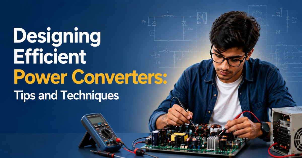
Power electronic converters are essential in today's world power systems and applications that include renewable energy systems, electric vehicles, and industrial automation. One fundamental purpose of these converters is conversion of electrical energy from one form to another (DC to AC or vice versa) and control of the power flow in the system. The power electronic converter design presents a rather challenging problem that must draw upon a thorough conceptual understanding of electrical engineering principles and a good grasp of mathematical modelling techniques.
Factors like high-efficiency design, high power density, and reliability all
put a significant challenge before the designer choosing power semiconductors,
capacitors, inductors, converter topology, and control strategy all play a role
in increasing efficiency. Minimizing EMI while ensuring acceptance of the EMC
standards is a major consideration in converter design.
In response to all these issues, researchers and engineers are forever trying to devise new design techniques and technologies includes advanced control algorithms, unique packaging and cooling solutions, and novel materials and components. The push for developing high-performance, energy-efficient power systems will continue to keep power electronic converter design on the cutting edge of research and development in electrical engineering.
We are going to help engineers achieve high-efficiency power converters by looking at the essential tips and tricks.
Choose the Right Topology
A buck converter is ideal for applications requiring efficient step-down of voltage. The boost converter is employed to increase voltage levels. When the input voltage can vary both above and below the output voltage, the buck-boost converter is useful. Flyback or forward converters are often used in isolated power supply applications.
✅ Tip: Before deciding on the topologies, the voltage range of input and output isolation requirements, and loading constraints are very important to consider.
Select High-Efficiency Components
However, choosing high-grade components with low power losses is absolutely essential.
• Employ MOSFETs/IGBTs with an associated R<sub>DS(on)</sub> and gate charge low enough to use.
• Inductors: employ high-efficiency cores with as little core and copper losses as possible.
· Capacitors: Lowest Equivalent Series Resistance (ESR) capacitors maximize ripple performance.
• Diodes: Use Schottky diodes or synchronous rectification to lessen conduction losses.
✅ Tip: Refer to the thermal performance and switching characteristics listed in the data sheet for more technical details.
Minimize Switching Losses
High-frequency switching could harness superior energy efficiency, a very admirable characteristic found in its nature however, if there are some ill effects, several losses or undesired impacts may still be perceived when not treated.
• Fast switching transistors and appropriate gate drivers must be utilized.
• Avoid all superfluous switching operations.
✅ Tip: The use of a scope helps inspect the changing waveforms, making it possible to fine-tune the timing and dead times.
Optimize PCB Layout
· High current paths should be kept short and wide.
· Separate noisy switching nodes from analogy signals.
· Ground properly, and minimize the areas of loops to reduce EMI.
· Thermal vias and copper pours should be used as much as needed for heat sinking.
✅ Tip: Do as reference designs say and simulate them with your layout to ascertain performance.
Implement Feedback and Control Loops
Well-regulated and rapidly transient responding converters are efficient.
• Incorporate precise voltage sensing and feedback loop.
• PID or digital control techniques may avail superior dynamic response.
• Input/output voltages, currents, and temperature monitoring.
✅ Tip: Adjust and smooth your control action by compensating and negating upsurge or diminishing in feedback signal.
Thermal Management
The efficient converters above are also a source of heat generation.
• Heat sink or spreaders should be for high-power components.
• Airflow into the enclosure must by improved.
• Sensor monitored with inbuilt thermal shutdown protection.
✅ Tip: Multiple ongoing changes depend on sustainability alternatively.
Test under Real Conditions
Make tests on the simulator with operational reality always put into consideration.
• Load under actual currents.
• Subject to voltage fluctuations.
• Carry out thermal checks under long-duration operation.
✅ Tip: Make use of electronic loads and environmental chambers where available.
Control Techniques for Power Electronic Converters
Electronics converters widely used in various areas, such as renewable energy systems, electric vehicles and industrial automation. Control of these converters is the key to ensuring their efficient and reliable operation. In this section, we will discuss some of the most common control techniques used as following.
Proportional-Integral-Derivative (PID) Control
There exists a quite popular control mechanism among power electronic converters called PID control. The PID controller generates an error signal by obtaining the difference between the desired output and the actual output and uses it in three domains – proportional, integral, and derivative terms – to generate the control signal. Indeed the proportional term provides a response directly proportional to this error; as for the integral term, it generates an output that's proportional to the integral of this error; meanwhile, the derivative term has an output reactant to the rate of change of this error.PID control is a popular control method uses feedback to adjust the output of the converter based on a difference between a desired output and the actual output. An error signal is obtained by taking the real output and subtracting the desired output then applying the three important terms such as proportional, integral and derivative to the error signal for further generation of control signal.
Model Predictive Control (MPC)
The technique of model predictive control (MPC) projections using theory-determined conservative modelling and algorithm-based analysis by achieving virtual control by prediction about optimally manipulating the performance of the converter through the models of systems connected to it. The calculated control signal of the MPC will be by considering optimization situations about the minimization of the function cost subject to the constraints on converter output and performance of the relative system. The similar control can be given with the converter output constrains such as voltage and current limits along with system performance constraints like the maximum power output and the minimum energy consumption by the application of temperature or dynamic constraints.Sliding Mode Control (SMC)
Applications of Power Electronic ConvertersThe application of converters is varied ranging from renewable energy systems up to electric vehicles. Below are some of the most interesting applications:
Renewable Energy Systems
Renewable energy sources like wind turbines and solar panels utilize converters in converting the DC power generated by such systems to AC through electronics converters in homes and businesses. In addition to the conversion, are useful in controlling the voltage and frequency of the AC output.Electric Vehicles
Industrial ApplicationsConsumer Electronics
They are sometimes called as power electronic converters. Other popular examples of these highly efficient devices, which are used everywhere in laptops to smartphones to televisions and all, are AC to DC converters, which convert AC to DC equipment and regulate voltage and current in consumer electronics. They are thus worthy components of consumer electronics, as they provide efficient, meaningful energy conversion from AC to DC or convert voltage into current levels with precise control.The design of a power converter might be quite efficient with a combination of good design, quality components, and thorough testing. These hints will assist you in upgrading the performance and reliability of the converter whether you are working on a solar inverter, EV charger, or embedded controller. Do you have a power converter design in question? Please express your design challenges or insights in the comment section below!
SMC is a control approach that uses a sliding surface for controlling the converter's output. The sliding surface is a hyperplane that divides the converter output into two regions: one in which the output is controlled and one in which it is not. The controller regulates the position of the converter output on the surface so that this output remains controlled. SMC can manage various nonlinearities and uncertainties in the converter or in the system to which it is connected, providing robust control.
Electronic graphics conversion involves the regulation of power delivery and control ability from an electrified battery to an electric motor propulsion system. It permits conversion, speed, and torque while being vitally important in electric vehicles. Power electronic converters enable an efficient transformation of energies, enabling controllable motor dynamics.
The applications of power electronic converters are in a
number of industries-from motor drives, welding machines sources. They can be
used for controlling motor speed and torque, regulating voltages and currents
in welding machines, and finally converting AC to DC for the purpose of power
supplies.
Conclusion
The design of a power converter might be quite efficient with a combination of good design, quality components, and thorough testing. These hints will assist you in upgrading the performance and reliability of the converter whether you are working on a solar inverter, EV charger, or embedded controller. Do you have a power converter design in question? Please express your design challenges or insights in the comment section below!
 Can Electric Vehicles Power Entire Cities? Understanding Vehicle-to-Grid (V2G) Technology
 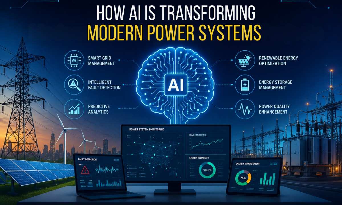 How AI is Transforming Modern Power Systems
  Power Electronics for Smart Grids: Enhancing Efficiency
  Introduction to Control Systems: Principles and Applications
  Control Strategies for Electric Drives: An Overview
  Electric Drives: Fundamentals & Key Components
  Applications of Power Electronics in Renewable Energy Systems
  Advances in Power Semiconductor Devices
  Power Electronics: Key Concepts and Applications
  Cybersecurity in Power Systems: Protecting Critical Infrastructure
  The Evolution of Power Transmission: From AC to HVDC
  Impact of Energy Storage on Power System Management
  Load Flow Analysis : Techniques and Applications in Power Systems
  Microgrids: Enhancing Resilience and Efficiency in Power Systems
  Innovative Technologies in Power System Protection
  Challenges and Solutions in Power System Stability
  Final Year Electrical Engineering Project Ideas for College Students
  The Role of Renewable Energy in Modern Power Systems
  Smart Grids: Revolutionizing the Future of Power Systems
  Automated Power Factor Correction: Improving Energy Efficiency
  Powering the Future: A Renewable Energy Harvesting System
  Smart Grid Solutions: Enhancing Electrical Distribution Efficiency
  Electric Vehicle Charging Infrastructure Design and Implementation
 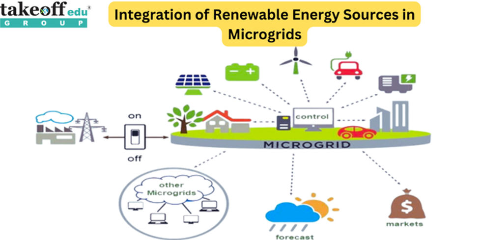 Integration of Renewable Energy Sources in Microgrids
  Electrical Projects Engineering Students
  M.Tech Thermal Engineering Projects
  IEEE Projects for Electrical Engineering
  Mini Projects for EEE
  Mini Projects for Electrical Students
  Top Electrical Projects for Final Year Students
  10 Interesting Projects for Electrical Engineering Students
  7 Trending Power Systems Based Projects for EEE
  Top 10 Power Electronics Projects for EEE
  Top 16 Electrical Engineering Projects
 Paper Publishing


