
Nearly every industry depends heavily on electricity, but mining engineering is particularly dependent on it. Miners' tasks would be difficult, if not impossible, to complete without it. However, mine sites are especially vulnerable to power outages since they are frequently situated at the edge of the grid and run using large mining equipment. Mining sites are finding it difficult to maintain their operational efficiency and competitiveness in the market due to the ever-rising cost of energy. Additionally, mines are typically targeted by electrical firms and allied organizations since they are also thought to be particularly major power users. For mines to optimize output, prevent technical issues, and save energy costs, maintaining power quality is essential. When the power factor becomes close to 1, it indicates that the system is making efficient use of all the energy that is delivered. However, in mine sites’, complicated machinery is frequently used, and power factor 1 is seldom attained. All power factors above.95 are recognized and regarded as energy-efficient uses in the mining industry. For a coal mine, the uncorrected power factor typically falls between 0.65 and 0.8. Reducing power factor to almost unity has the advantages of lowering utility costs, resolving technical problems, reducing carbon footprints, honouring legal obligations, and more. Therefore, appropriate corrective equipment must be built to keep an eye on the system power factor and adjust as needed when it falls below the designated threshold established in accordance with the regulations.
Power Factor Correction
To lower expenses imposed by the electricity supplier, consumers can implement power factor correction themselves, or the electrical utility can apply it to improve the stability and efficiency of the transmission network.
Capacitors are used in manual power factor adjustment to reduce reactive power and raise the power factor. But this process takes a lot of time and is frequently ineffective. This is when the automated power factor correction is useful. Real-time power factor analysis and continuous monitoring are features of automated power factor correction systems. The ideal quantity of reactive power needed at any particular time is determined by these systems using sophisticated algorithms and control circuits. To keep the power factor close to unity, they automatically turn on and off capacitors and other PFC components.
Reasons of Low Power Factor
Mercury vapour lights or choke-operated lights
Completely empty transformers have very low power factors and are very inductive.
The state of load and unload in induction motors.
Low power factor in the mines is caused by inductive load equipment such as conveyors, drills, hoists, shovels, pumps, and shearers, among others.
Automatic Power Factor Correction
In electrical engineering, automatic power factor correction, or APFC, is a technique used to control and enhance an electrical load's power factor. A system's efficiency in using electrical power is gauged by its power factor. It represents how well the current is being transformed into usable work and is calculated as the ratio of actual power (measured in watts) to perceived power (measured in volt-amperes).
Significance of Automatic Power Factor Correction
In electrical engineering, APFC is very significant for a few reasons:
Energy Efficiency
Reactive power requires less generation and transmission when APFC technologies increase the power factor. As a result, power distribution systems have less energy losses and use electrical power more effectively.
Lower Energy Expenses
The power factor of commercial and industrial customers is a determining element for many utility companies. Because of the penalties associated with low power factor usage, a low power factor raises electricity expenditures. To avoid these fines, APFC systems keep their power factor high.
Best Use of Resources
Electrical systems can function effectively thanks to APFC technologies. Utilities may save money and improve grid management by better allocating their resources by lowering the requirement for reactive power generation.
Enhanced Control of Voltage
Distribution systems' voltage control can be enhanced via power factor correction. To maintain linked equipment operating within defined voltage limits, reactive power consumption-related voltage drops are minimized.
Prolonged Life of Equipment
Poor power factor inductive loads drain excessive current from the source, adding to the strain on electrical components including transformers, motors, and cables. These loads can run on less current by increasing the power factor, which could lengthen the equipment's lifespan.
Release of Capacity
Distribution networks can have more capacity thanks to power factor adjustment. An infrastructure may support larger loads without being overloaded when there is an improvement in power factor, which lowers the amount of current passing over the system.
Effect on the Environment
By cutting down on energy losses and the requirement for excessive power generation, APFC systems help to promote environmental sustainability. Reducing greenhouse gas emissions linked to the generation of energy can result from this.
Respect for Regulations
Certain industrial facilities are required by rules or standards in many countries to maintain a specific power factor. Industry compliance with these regulations and avoiding legal ramifications are facilitated by APFC systems.
Stability and Dependability
APFC systems add to the overall stability and dependability of electrical grids by preserving a balanced power factor. Unpredictability and voltage swings can result from uncontrolled reactive power.
The capacity of automated power factor adjustment to improve equipment performance, reduce costs, increase energy efficiency, and promote sustainable power distribution and consumption is essentially a crucial component of contemporary electrical engineering.
Improving Energy Efficiency
The primary goal of automated power factor correction is to assist in balancing the industry's surplus reactive power produced by inductive loads. By decreasing losses and apparent power demand charges, the industry may increase system efficiency through the effective usage of this device. Hence getting rid of TNB's low power factor fines. The target power factor of 0.90 is a compelling figure since it provides the power factor adjustment system with enough control capabilities.
The European Community reports that the industrial and service sectors account for 94% of the demand for reactive power. Reactive and active energy combined decreases from 3173 TVAh (without power factor adjustment) to 2730 TVAh when these sectors keep their power factor at 0.95. This translates into 15% drops, which lowers network loads and minimizes network losses.
According to Alpes Technologies, one of the French manufacturers of power factor correction panels, the transformer will get more power after the industry's power factor has been adjusted to a specific level. The transformer may receive up to 7% more power, for instance, if the power factor value is adjusted to 0.8. Additionally, there would be around 33% more power going to the transformer if the power factor value had achieved the optimal value of 1.0.
Applications of Capacitors in APFC
Using contactors to switch between many capacitors, an automated power factor correction device is built. A regulator that monitors the power factor of a motor or an electrical network controls these contactors. In order to maintain the power factor above a certain value, this guarantees that only the necessary capacitor is activated based on the load and power factor of the network. The most straightforward and affordable method of power factor adjustment for this kind of application is often a fixed capacitor.
With the exception of creating leading power factor loads, a capacitive load bank functions and is rated similarly to a reactive load bank. The telecommunications, computer, and UPS sectors are known for using specific electronic or nonlinear loads, which these loads mimic. To ensure that a power factor capacitor with the correct value is always attached to the system, an automated capacitor system should be employed for numerous loads. For this reason, the automated power factor correction is formed by a microprocessor.
Power Factor Calculation
You must know your actual power (P), reactive power (Q), and apparent power (S) to compute your power factor. Optionally, you may estimate them based on your equipment's specs or use a power or clamp meter to measure them. Power factor is calculated as follows: Power factor = P / S
The formula for apparent power is: S = sqrt(P^2 + Q^2)
To make things easier, you may also utilize an online power factor calculator.
Selection of Power Factor Correction Device
For power factor correction, selecting the appropriate capacitor is crucial. Considerations include the capacitor's placement and size, the system's voltage and frequency, the kind and quantity of inductive loads, and the power factor that is now present and that is required. Payback time and cost are other significant factors to consider. A capacitor size calculator is available online to help with this procedure.
Installation and Maintenance of Power Factor Correction Device
To guarantee safe and effective functioning, you should hire a skilled electrician or contractor to install and maintain your power factor correction device. Doing it yourself is not recommended. Choosing and buying the right device and accessories, installing, and wiring the device in accordance with local codes and manufacturer instructions, commissioning and testing the device to confirm savings and performance, and routinely monitoring and inspecting the device are all part of this process. A site survey and load analysis are also conducted to identify opportunities and needs for power factor correction. Power factor correction can be utilized in these phases to improve power distribution and planning, resulting in cost savings and increased energy efficiency.
Power Factor Compensating Devices
In essence, the power factor compensating devices provide the system with the reactive power needed to raise the power factor and voltage profile. The most popular compensating mechanism in use today is the shunt capacitor.
Capacitive Compensators
Industrial distribution networks make considerable use of shunt capacitors. As an inductive load requires an out-of-phase component of current, they provide reactive power to offset that requirement. By using shunt capacitor banks, the source-current is reduced in magnitude, the power factor is increased, and as a consequence, the system's overall voltage control is improved. Beyond their use, shunt capacitor banks have no effect on current or power factor. Fixed, switching, or a mix of both types of capacitor banks are available. Both automated and manual switching process are possible. Battery banks are robust and easy to set up and maintain. The installation of power-factor correction capacitors in high-voltage power centers is a matter of concern for the U.S. Department of Labor's Mine Safety and Health Administration (MSHA). MSHA believes that each capacitor bank should have a different built-in method for discharging the capacitors, even when the capacitors include bleeder resistors.
Synchronous Condensers
Battery banks are robust and easy to set up and maintain. The installation of power-factor correction capacitors in high-voltage power centers is a matter of concern for the U.S. Department of Labor's Mine Safety and Health Administration (MSHA). MSHA believes that each capacitor bank should have a different built-in method for discharging the capacitors, even when the capacitors include bleeder resistors. Because of this, their use in the mining sector has been restricted, except for situations in which recovered ones were offered at a competitive price. The following factors need to be considered before beginning any installation:
Reliability of the equipment to be installed.
Probable life.
Capital cost.
Maintenance cost.
Running Costs.
Space required and ease of installation.
Top Power Factor Correction Projects
Top Power Factor Correction Projects are listed in this section.
 Can Electric Vehicles Power Entire Cities? Understanding Vehicle-to-Grid (V2G) Technology
  How AI is Transforming Modern Power Systems
  Power Electronics for Smart Grids: Enhancing Efficiency
  Introduction to Control Systems: Principles and Applications
  Control Strategies for Electric Drives: An Overview
  Electric Drives: Fundamentals & Key Components
  Applications of Power Electronics in Renewable Energy Systems
  Designing Efficient Power Converters: Tips and Techniques
  Advances in Power Semiconductor Devices
  Power Electronics: Key Concepts and Applications
  Cybersecurity in Power Systems: Protecting Critical Infrastructure
  The Evolution of Power Transmission: From AC to HVDC
  Impact of Energy Storage on Power System Management
  Load Flow Analysis : Techniques and Applications in Power Systems
  Microgrids: Enhancing Resilience and Efficiency in Power Systems
  Innovative Technologies in Power System Protection
  Challenges and Solutions in Power System Stability
  Final Year Electrical Engineering Project Ideas for College Students
  The Role of Renewable Energy in Modern Power Systems
  Smart Grids: Revolutionizing the Future of Power Systems
  Powering the Future: A Renewable Energy Harvesting System
  Smart Grid Solutions: Enhancing Electrical Distribution Efficiency
 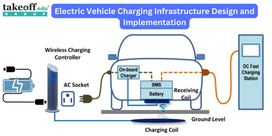 Electric Vehicle Charging Infrastructure Design and Implementation
  Integration of Renewable Energy Sources in Microgrids
  Electrical Projects Engineering Students
  M.Tech Thermal Engineering Projects
  IEEE Projects for Electrical Engineering
  Mini Projects for EEE
  Mini Projects for Electrical Students
  Top Electrical Projects for Final Year Students
  10 Interesting Projects for Electrical Engineering Students
  7 Trending Power Systems Based Projects for EEE
  Top 10 Power Electronics Projects for EEE
  Top 16 Electrical Engineering Projects
 Paper Publishing


