Clap switch
Objective
The main objective of this project is to switch ON/OFF the load by clapping
Abstract
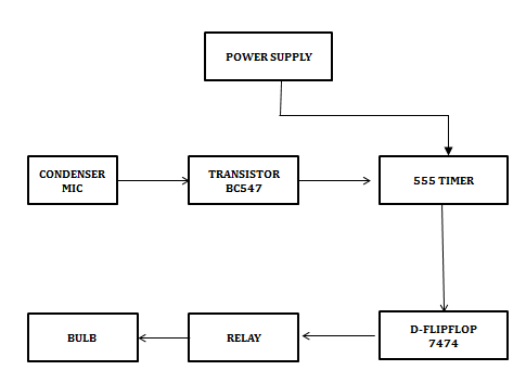
A Clap switch is an interesting concept that could be used in home automation. It works as a switch which makes devices ON and OFF by making a clap sound. Although its name is “Clap switch”, but it can be turned ON by any sound of about same pitch of Clap sound. The main component of the circuit is the Electric Condenser Mic, which has been used as a sound sensor. Condenser Mic basically converts sound energy into electrical energy, that in turns used to trigger 555 timer IC, through a Transistor. And triggering of IC 555 TIMER works as a Clock pulse for D-type flip-flop and would turn ON the LED, which will remain ON until the next clock pulse means until the next Clap/sound. So this is the Clap Switch which will turn ON with first Clap and turn OFF with the second Clap. If we remove the D-type Flip flop from the circuit, the LED will be turned OFF automatically.
This is a project on CLAP SWITCH which can switch on/off any electrical circuit by the sound of a clap. The operation of the circuit is simple. If we clap the lamp turns on and to switch it off clap again. The condenser microphone picks up the sound of your claps, coughs, and the sound of that book knocked off the table. It produces a small electrical signal which is amplified by the succeeding transistor stage. Transistor connected to a monostable multi vibrator change state at each signal. Transistor output is given to input pin of 555timer IC. The output of monostable multivibrator is given to D flip-flop to controls a lamp using relay.
This circuit can switch on and off a light, a fan or a radio etc. by the sound of a clap. This circuit is constructed using basic electronic components like resistors, transistors, relay, transformer, capacitors. This circuit turns ON light for the first clap. The light turns ON till the next clap. For the next clap the light turns OFF. This circuit works with 12V voltage. Therefore a step-down transformer 12V/300mA is employed. This working of this circuit is based on amplifying nature of the transistor, switching nature of transistor, and relay as an electronic switch. Basically, this is a Sound operated switch.
Keywords: Flip Flop Circuit, Circuit Amplifier, Bc547 Transistor, IC555 Timer, IC7474, and Bulb.
NOTE: Without the concern of our team, please don't submit to the college. This Abstract varies based on student requirements.
Block Diagram

Specifications
Hardware Requirements:
- Condenser MIC
- Power Supply
- 555 Timer IC
- BC547 Transistor
- Edge Triggered D- FlipFlop
- Relay
- Bulb
- Capacitors
- Resistors
Learning Outcomes
- 555 IC diagram and Architecture
- Working of 555 timer and its modes
- Giving condenser mic input to the 555 timer through a transistor
- Circuit analysis and designing
- Timing delay calculation of the designed circuit
- Controlling of load through the designed circuit
- About Project Development Life Cycle:
- Planning and Requirement Gathering(Hardware components)
- Schematic preparation
- Hardware development
- Development of the Project and Output testing
- Practical exposure to:
- Circuit designing
- Solution providing for real time problems,
- Working with team/ individual,
- Work on Creative ideas.
- Project development Skills
- Problem analyzing skills
- Problem solving skills
- Creativity and imaginary skills
- Project presentation skills


 Paper Publishing
